Perspective Drawing by Hand – Hand or computer drawing?
(to go straight to computer aided perspectives)
When I first started in this industry I was taught to do perspective drawing by hand on a drawing board. We used these to help our client and ourselves visualise the finished interior three dimensionally. It was a reasonably complicated exercise but with practice it soon became quick and the results were enough to do the job.
When computer aided design and drafting first arrived on the market, I tried to use it but found it limited, cumbersome and slow. It was also very complicated to use. Happily for me all that has changed and the programmes that are available now are intuitive and easy to use.
This article shows how to draw a single point perspective and then you can follow on to learn the difference between that and using a computer program to help you develop your design skills. Perspective drawing by hand doesn’t need to be complicated and with a little practice and learning about simple rendering techniques it will become a valuable tool . Perspective drawing by hand a sketch to demonstrate an idea to your client will show how skilled you are and saves an immense amount of time.
This exercise will show you how to draw a single point perspective. On the following pages an example of single point perspective is shown. Study this closely and then, if desired, as an exercise draw the perspective by following the steps. The drawing is at a scale of 1:50 (before being transferred into the computer, so is now irrelevant.) but if you don’t have a comprehensive knowledge of drafting don’t be too concerned as this exercise is to help you see how both systems are used. The final drawing will give you a perspective sketch that is able to be to rendered with lines of texture or color.
Draw all lines lightly in pencil initially until you come to the rendering stage of the drawing. Then you may use pencil and ink and “firm up” (darken) the lines and add the texture to render the drawing and give it contrast as well as depth.
Step 1
Draw a plan of a room. Copy the one depicted for your first attempt. It shows a simple kitchen. There are cabinets, the tiled floor, window and a door. This drawing is at 1-50 so you will be able to use your scale ruler to work out the sizes.
Step 2
You now will draw an outline of the front edge of the room that you are going to view. Essentially this is an outline of the elevation of the room. To this add the height of the room, the window and door and cabinets and also mark on the bottom edge where the tiles will be. You can project (projection lines) down from the plan and across from the elevation or section to establish the heights and floor positions or simply measure from the plan and elevation and a mark on the edges of the elevation or outline edges of the room. Use the vertical lines for height and horizontal baseline for widths or positions of objects.

Step 1 and 2
Step 3
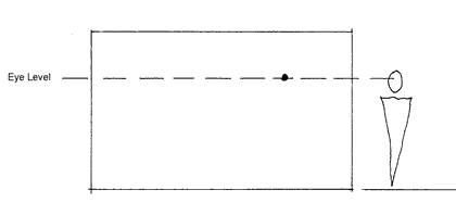
On that same elevation we need to establish what height we are looking from and where we are looking. Eye level is the height and the vanishing point is where we are looking. Eye height for a tall male is about 1600 to 1700 millimetres from the floor and for a female 1400 to 1500 from the floor. The vanishing point should not be in the middle of the room or too close to the edges of the room.
Step 4
You now or in need to link the corners of the room to be vanishing point. The divisions that mark where the tiles are should also have a line drawn from them to the vanishing point.
Step 3 and 4

Step 5
We now select a “spectator” spot outside of the view but on the same height line as the eye level line and the vanishing point. From this point (usually to the opposite side of the vanishing point and the same distance out,) draw a line to the far bottom corner. Where this line intersects the tile lines heading towards the vanishing point, draw horizontal lines across. These form the depth of the tiles (at 300 millimetres divisions or one foot divisions). This grid that you now see is based on 300 millimetres each way and can be used to determine positions and sizes of objects that you may wish to add.eg a table or chair or vase of flowers.
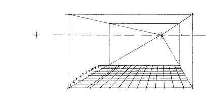
Step 5
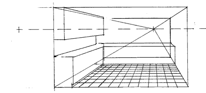
Step 6
Count back the lines from the front edge to determine the depth of the room (in this case10). At the end of the end of the 10th tile is the end of the room (confirm this by counting back on the plan.
Draw the two vertical lines on the intersection of the horizontal line for tile 10 and the vanishing (angled) lines of the each other rooms. Now draw the horizontal ceiling line across. You have now created the box of the room.
Step 7
Draw the ends of the furniture (cabinetry) and project these lines back toward the vanishing point to create the outlines of the furniture. Draw the base of the cabinets (if you haven’t already done so as well).
Where the lines intersect the vertical lines are drawn. The height of the vertical lines is determined by using the information in drawn in step 2 and transposing it along the front each of the room back to be vanishing point.
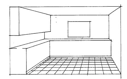
Step 8
There you have a simple method of perspective drawing by hand. You can now start adding the detail and rendering your drawing. Note for this exercise we are not attempting to draw in exact perspective so the heights and sizes of door handles, the size of graining etc doesn’t have to be exact. Photocopy this final layout and practice your rendering technique.